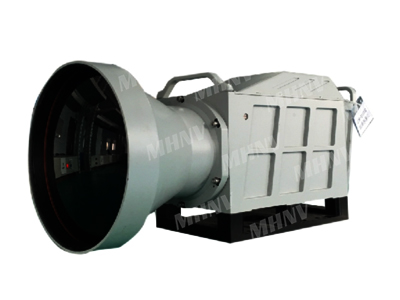
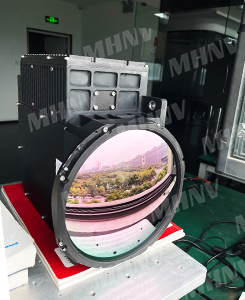
1280*1024/640*512 Cooled Thermal Core with 50-1100mm Continuous Zoom
VIDEO
MH MW-50- 1100 thermal imager (hereinafter referred to as " MW-5--100 ") is integrated in various typ es of photoelectric systems. It is mainly used to complete infrared detection, identification, recognition and reconnaissance, int elligence gathering, targeting, etc. of targets at night or under bad weather conditions.
1 Requirements for functions and main technical indicators
1.1 Features
1) Manual focusing, which ca n read the current focal length value and provide a focal length value.
2) Manual zoom, can read the zoom value, and can provide the zoom value.
3) Automatic focusing.
4) Black hot/white hot polarity conv ersion.
5) Manually and automatically adjust brightness and contrast.
6) Bad pixel replacement.
7) NUC.
8) Adjustment of integration time.
9) Digital zoom: 2x, 4x.
1.2 Requirements for main technical indicators
1) Detector
Table 1 Detector indicators
Item
indicators
Response band
3μm ~ 5μm( nominal value )
Array specifications
1280×1024
Pixel size
15μm
NETD
NETD ≤25 mk ( @25℃ )
F- number
5.5
Bad pixel rate
≤0.5%
Focal plane operating temperature
≤82K ( design guarantee )
2) Optical system indicators
a) Electric continuous zoom lens. Focal length: 50~ 1100mm.
b) F- number : 5.5
c) The parallelism between the optical axis and the installation base shall not
exceed 0.5mrad.
d) Minimum focal distortion ≤ 3% (design gua rantee).
3) Start time
The startup time of the entire machine is ≤ 9 minutes ( full temperature range ).
4) Continuous working hours
The continuous working time of the entire machine shall not be less than 10 hours.
2 Size and weight
1) Overall dimensions ≤500mm×235mm×290mm ( L×W×H ) . ( Please refer to the attachment for details )
2) Weight : ≤11.0kg 。
3 Electrical interfaces and protocols
1) Power supply voltage: DC stabilized power supply 24V ± 2V, working curre nt not exceeding 1.5A.
2) Analog video outp ut: 1 channel PAL analog video.
3) Digital video output: 1 CameraLink, digital progressive scanning, frame rate ≥ 25 frames/second.
4) Communication interface and protocol: see Annex 1 for details.
5) Electrical interface definition: see Annex 2 for details.
4 Environmental adaptability
1) Operate temperature : -40℃ ~ +60℃ ;
2) Storage temperature : -45℃ ~ +70℃ ;
3) Vibration and shock: sh ock waveform: half sine wave; The duration of 15G is 3 times in each direction of the vertical, vertical, and horizontal axes (11ms ± 2ms).
5 Packaging require ments
Safety protection transport box.
Annex 1
Appendix Table 1 Data Format Sent by Upper Computer to Thermal Imager
Communication protocol : RS 422, full duplex .
Communication format : 1 bit start bit , 8 bits data bit , 1 bit stop bit , no parity check
Baud rate : 38400b/s
No
Command
Description
1
Sync Header 1
0 xEB
2
Sync Header 2
0x90
3
Command
See Appendix Table 2 for details
4
Backup (0)
Zoom lens position , 8 bit low
5
Backup (1)
Zoom lens position, 8bit high
6
Backup (2)
0x00
7
Backup (3)
0x00
8
Checksum
3-7 byte checksum
Appendix Table 2 Oper ation Command
No
Command
Description
Code
1
IR Focus +
Focal position adjustm ent
0x83
2
IR Focus -
Focal position adjustm ent
0x84
3
Auto Focus
Auto Focus
0x61
4
IR Large FOV
Increase field of view
0x85
5
IR Small FOV
Reduce field of view
0x86
6
IR Positive/Negative P olarity Switch
Backup [0]=0 ( Cyclic switching polarity )
Backup [0]=1 ( White hot )
Backup [0]=2 ( Black hot )
0x87
7
IR Integral Time +
Increase integration time
0x88
8
IR Integral Time -
Reduced integration ti me
0x89
9
Correction
Non-uniformity correction
0x8A
10
E- zoom 2x , 4x
Backup [0]=0 ( cyclic switching
electronic zoom coe fficient)
Backup [0]=1 (1 x electronic zoom )
Backup [0]=2 (2 x electronic zoom )
Backup [0]=4 (4 x electronic zoom )
0x8B
11
IR Brightness and Contrast Manual Adjust
Manual adjustment of bright ness and contrast
0x8C
12
IR Brightness and Contrast Auto Adjust
Automatic adjustment of brightn ess and contrast
0x8D
13
IR Brightness +
Brightness increase
0x8E
14
IR Brightness -
Brightness reduction
0x8F
15
IR Contrast +
Contrast increase
0x90
16
IR Contrast -
Contrast reduction
0x91
17
IR Edge Sharpen +
Edge enhancement increase
0x63
18
IR Edge Sharpen -
Edge enhancement reduction
0x65
19
IR Output Self-check Image
When the thermal imager receives 0x94,
the device outputs a self inspecti on
image; When the thermal imager
receives other control commands, the
device outputs a normal image.
0x94
20
Blind Filling
Blind Filling
0x02
21
Manual Blind Filling
Manual Blind Filling
0x20
22
Saving Data
Saving Data
0x21( Send 2 times in 10S)
23
Cross on/off
Cross on/off
0x22
24
Cross H +
Cross H +
0x23
25
Cross H -
Cross H -
0x24
26
Cross V +
Cross V +
0x25
27
Cross V -
Cross V -
0x26
28
Reset Cross
Reset Cross
0x27
29
Background Correction
Background Correction
0x28
30
Lens Setting
Zoom position setti ng Backup [0] ( Low 8 bit ) Backup [1] ( High 8 bit )
0x29
31
Focus Setting
Focus position setting Backup [0] ( Low 8 bit ) Backup [1] ( High 8 bit )
0x2A
32
Image Flip
Backup [0]=0 ( loop switching ) Backup [0]=1 ( normal image ) Backup [0]=2 ( Image flipping )
0x2B
Appendix Table 3 Da ta Format for Sending Thermal Imager to Upper Computer
No
Command
Description
1
Sync Header 1
0 xEB
2
Sync Header 2
0x90
3
IR Lens Value
Zoom lens position , 8 bit low
4
IR Lens Value
Zoom lens position , 8 bit high
5
Status Bit
Status bit, See Appendix Table 4 for details
6
IR Focus Value
Focus lens position , 8 bit low
7
IR Focus Value
Focus lens position , 8 bit high
8
Checksum
3-7 byte checksum
Appendix Table 4 Status Bit
Bit No .
Description
D7
IR Status
=0 Normal ; = 1 Fault
D6
Image Status
=0 Normal Image ; = 1 Test Image
D5
Cooler Fault
=0 Normal ; = 1 Fault
D4
Imager Self-check Status =0 Normal ; = 1 Fault
D3
Communication Status of Serial Port that receive in-done master co ntrol =0 Normal
= 1 Fault
D2
Temp Alarm =0 Normal = 1 Fault
D1
XX
D0
XX
Annex 2
Thermal imager extern al connector model: J30V2-25TJ -L1. One set o f
corresponding connectors should be provided for the enti re machine.
Appendix Table 5 Definition of External Connectors f or Thermal Imagers
Pin No .
Definition
Requirement
1 、 2 、 12
VIN 24V
Twisted-pair
3 、 4 、 13
GND 24V
5
GND 3.3 V RS 422
6
RX 0+
Twisted-pair
7
RX 0-
8
TX 0+
Twisted-pair
9
TX 0-
10
PAL_GND
11
PAL
14
GND CAM
15
GND CAM
16
CLK +
Twisted-pair
17
CLK -
18
X3+
Twisted-pair
19
X3-
20
X2+
Twisted-pair
21
X2-
22
X1+
Twisted-pair
23
X1-
24
X0+
Twisted-pair
25
X0-
Different lens available:
Request A quick Quote (WhatsApp:+ 86-18792456795)