187 9245 6795
Email: mh_elec@126.com or jacky@mh-elec.com
Introduction to Mobile anti-drone system
1. Missions and operational use requirements
The mobile anti-drone system can be deployed in anti-terrorist and stability
maintenance forces, border and naval defence forces, overseas peacekeeping forces, as
well as air defence forces and electronic countermeasures forces to interfere with and
destroy small/micro drones and protect key areas, key regions and major events.
The mobile anti-drone system adopts composite detection and layered
countermeasures, including: detection and targeting, radio detection and interference,
laser interception.
The UAV search and discovery mainly has two methods: passive radio detection and
active radar detection.
The UAV countermeasure mainly has two ways: radio interference and laser
interception. While the radio interference acting at a far distance and covering a wide
airspace to achieve the effect of repulsion or forced landing. And the high-energy laser
interception acting at a relatively close distance and on point targets to achieve a reliable
physical attack.

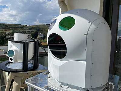
Figure 1: Mobile anti-drone system in combat condition in live view

Figure 2: Mobile anti-drone system in marching condition in live view

2. Equipment components and main functions
2.1 Equipment composition
The mobile anti-drone system mainly consists of an integrated control subsystem,
laser subsystem, optoelectronic tracking launch subsystem, chassis and structure
subsystem, power subsystem, radar subsystem, radio detection subsystem, radio
interference subsystem, navigation deception equipment, simulator trainer and other
components.


Figure 3: Diagram of the components of the mobile anti-drone system
2.1.1 Integrated control subsystem
The integrated control subsystem consists of an integrated control electronic box,
display and control equipment, positioning and directional communication equipment,
etc.
The integrated control subsystem is connected to other subsystems through the
internal data communication network to complete system workflow control and system
data management, it is connected to the higher command system or other mobile
anti-drone system through communication equipment to realize network operations.
2.1.2 Laser subsystem
The laser subsystem consists mainly of the laser, the beam combiner and the
thermostat.
The laser generates a high power laser output, the multiple lasers are combined to
achieve a coaxial laser output, the thermostat uses a storage cooling mode of operation to
control the laser at the set operating temperature.
2.1.3 Optoelectronic tracking launch subsystem
The optoelectronic tracking launch subsystem consists of an infrared thermal imager,
4light vision camera, laser rangefinder, emission telescope, laser illuminator, servo
turntable and other equipment.
Infrared thermal imager and light vision camera detect and image the target, the
system obtains information about the target's position by calculated. The laser rangefinder
is used for distance measurement of the target and provides an accurate amount of
focusing information for the laser emission. The emission telescope is primarily used to
achieve the precise focusing function of the high power laser at the target. The laser
illuminator is used for night illumination and provides the illumination conditions for fine
tracking imaging. A servo turntable is used to achieve high precision tracking of the
target.
2.1.4 Power supply subsystem
The power supply subsystem consists of a power take-off generator and an energy
storage and conversion power supply.
The generator is a power take-off generator, which obtains power from the power
take-off shaft of the vehicle engine, drives the generator to rotate, generates alternating
current (AC) and outputs this AC into direct current (DC) to the high voltage DC bus.
The main function of the energy storage and conversion power supply is to store and
release electrical energy through the energy storage battery and conversion power supply.
2.1.5 Chassis and structural subsystem
The chassis and structure subsystem consists of the chassis, the vehicle's square
cabin and the electric exhibition and withdrawal equipment.
The chassis is a 6 x 6 chassis, which meets the requirements of high mobility and
rapid arming. The vehicle's square cabin provides good protection against rain and dust
for the equipment inside the vehicle, and the electric exhibition and withdrawal
equipment realises rapid electric exhibition and withdrawal of the system.
2.1.6 Radar subsystem
The radar subsystem consists of an RF front-end, an information processing unit, a
5servo control unit, etc.
The radar subsystem adopts Ku-band radar with azimuth mechanical scanning and
pitch phased array scanning, which can effectively detect low-altitude targets such as
UAVs in the coverage area, form target track information including distance, azimuth,
altitude, pitch, speed and heading information of the target by automatic and
semi-automatic means, and have data recording capability and tactical replay capability.
2.1.7 Radio detection subsystem
The radio detection subsystem consists of an omnidirectional antenna array
detection antenna and a detection mainframe.
The radio detection subsystem receives radio signals in the 0.6GHz to 6GHz band,
determines whether they are UAV downlink communication signals through signal
feature analysis, and directs jamming equipment to interfere with UAV communication
links and GPS navigation links respectively to drive away or force down UAVs.
2.1.8 Radio interference subsystem
The radio interference subsystem consists of interference transmitting antennas,
amplifiers, etc.
The radio interference subsystem can suppress radio signals at any frequency point within
0.6GHz to 6GHz, including jamming the satellite positioning signal and control link
signal of UAVs to make them land automatically or force them to return, with the features
of full-frequency jamming, long-distance interception and easy operation.
2.1.9 Navigation deception equipment
The navigation deception equipment consists of a receiving antenna, a transmitting
antenna and a host of equipment.
Navigation spoofing equipment is capable of simulating satellite navigation
spoofing signals to create an all-day, all-round protection zone in a designated area,
which can be used to spoof UAVs flying with navigation.
2.1.10 Simulation trainer (optional)
6The simulator mainly consists of two sets of display and control equipment, a
simulation training server, etc.
Two sets of display and control equipment are identical to the models on the equipment,
simulating two battle stations, and a simulation training server is used to run simulation
training software and to implement simulation training calculation functions.
2.2 Main functions of the equipment
The mobile anti-drone system has the following main functions.
2.2.1 Detection function
(1) Detection, tracking and identification functions for small/micro UAV target.
(2) Locate the flight control operator (group use mode).
(3) Video recording of the interception and disposal process.
(4) The radio detection subsystem can be used off-board.
2.2.2 Interference/interception function
(1) Suppress and interfere the remote control signals of small/micro UAV, as well as
suppress and spoof the navigation signals.
(2) Suppress and interfere the small/micro UAV optoelectronic imaging payloads.
(3) Intercept and destroy the small/micro UAV.

3. Main tactical technical indicators
3.1 Object of combat
Small/Micro UAV (mainly including consumer grade UAV, industrial grade UAV
and simple assembly UAV etc.)
3.2 Combatants and duties
The combat crew consists of three persons, one driver and two operators. One driver,
who is also the battlefield guard, is responsible for driving the vehicle and guarding the
site, one operator, who is the vehicle commander, is responsible for operational command
and the operation of radar and radio detection equipment, and one operator, who is the
7gunner, is responsible for capture and tracking and laser damage operations.
3.3 Methods of detection
3.3.1 Remote telemetry signal direction finding and positioning (group use mode)
3.3.2 Radar detection.
3.4 Radio detection
3.4.1 Radio detection range: not less than 4 km (typical target: DJI PHANTOM 4,
EIRP of 100 mW, through-view conditions).
3.4.2 Detection frequency band: 600 MHz to 6 GHz.
3.4.3 Direction finding accuracy: better than 5° (RMS)
3.4.4 Frequency measurement accuracy: better than 1 MHz.
3.4.5 Pitch coverage range: -15° to 30°.
3.4.6 Response time: not more than 5s (UAV flight height 200m hovering in position
to the final detection data output, including radio signal reception, signal processing,
signal analysis and signal direction finding).
3.4.7 Requirements for off-vehicle use: 2 operators, the changeover time from the
working state of the team member on the vehicle to the working state under the vehicle is
no more than 1 hour, the changeover time from the working state of the team member
under the vehicle to the working state on the vehicle is no more than 1 hour, 220V mains
electricity is used, and an Ethernet communication interface is adopted.
3.5 Radar detection
3.5.1 Operating frequency: Ku band.
3.5.2 Operating system: azimuthal mechanical scanning, pitch phased array
scanning.
3.5.3 Maximum detection distance: not less than 5 km (typical target: "DJI
PHANTOM 4", detection probability not less than 90%).
3.5.4 Minimum detection distance: no greater than 0.3 km.
3.5.5 Distance measurement accuracy: better than 10 m (RMS)
3.5.6 Azimuth measurement accuracy: better than 0.4° (RMS)
3.5.7 Pitch measurement accuracy: better than 0.6° (RMS)
3.5.8 Azimuth scanning range: n x 360°.
3.5.9 Pitch scanning range: 0° to 30°.
3.5.10 Scan period: not more than 5s.
3.5.11 Number of targets to be tracked simultaneously: not less than 20 batches.
3.5.12 Minimum speed of radial flight of detectable targets: not more than 3m/s.
3.5.13 Maximum speed of radial flight of detectable targets: not less than 50m/s.
3.5.14 Pitch scan baseline adjustable range: not less than 20°.
3.6 Blocking methods
3.6.1 Radio suppression interference.
3.6.2 Navigation deception.
3.6.3 Laser damage.
3.6.4 Laser dazzling blindness.
3.7 Radio suppression interference
3.7.1 Operating frequency band: 600 MHz to 6 GHz.
3.7.2 Remote link suppression interference distance: not less than 3 km (typical
target: DJI PHANTOM 4, jam-to-signal ratio not less than 10:1).
3.7.3 Navigation suppression interference distance: not less than 3 km.
3.7.4 Navigation interference types: GPS (L1, L2), GLONASS (L1, L2), BDS (B1,
B3) civil navigation signals.
3.7.5 Jamming reaction time: not more than 5s (from the discovery of the target,
alignment with the target to the emission of the jamming signal, the turntable is rotated
180°).
3.7.6 Azimuth coverage: not less than 20°.
3.8 Navigation deception jamming
3.8.1 Deception jamming distance: not less than 1 km (typical target: "DJI Genie"
4).
3.8.2 Type of navigation jamming: civil satellite navigation signals from GPS (L1,
L2), GLONASS (L1, L2), BDS (B1, B3).
3.8.3 Navigation signal intrusion time: not more than 3 s.
3.8.4 Deception method: Omni-directional deception.
3.8.5 Working speed requirement between travels: no greater than 60 km/h.
3.9 Laser damage
3.9.1 Maximum damage distance: not less than 1500 m (typical target: DJI
PHANTOM 4, moderate atmospheric turbulence, visibility not less than 10 km).
3.9.2 Minimum damage distance: not more than 100 m (typical target: DJI
PHANTOM 4, moderate atmospheric turbulence, visibility not less than 10 km).
3.9.3 Maximum damage time: not greater than 10 s (typical target: DJI PHANTOM
4, moderate atmospheric turbulence, atmospheric visibility not less than 10 km).
3.10 Laser blinding and laser glare
3.10.1 Glare distance for optoelectronic imaging systems: not less than 3 km (under
conditions where the laser transmission of the target optical system is greater than 90%).
3.10.2 Blinding distance for optoelectronic imaging systems: not less than 2 km (for
optical systems with laser transmittance greater than 90%).
3.11 Lasers
3.11.1 Laser wavelength: 1060 to 1080 nm.
3.11.2 Continuous laser output power: not less than 20 kW.
3.11.3 Laser beam quality: no greater than 4.
3.11.4 Laser electro-optical efficiency: not less than 30 %.
3.11.5 Continuous working time: not less than 120 s.
3.11.6 Maximum working interval: not more than 25 min.
3.12 Optoelectronic tracking launch
3.12.1 Laser transmission efficiency for optoelectronic follow up scanning: not less
than 85%.
3.12.2 Optical transmitting antenna aperture: not more than 400 mm.
103.12.3 Capture and tracking distance: not less than 2 km (visibility not less than 10
km, humidity not greater than 60%).
3.12.4 System response time: not more than 6 s (from the time the target is detected
by the radar to the time when the laser is ready to fire and the optoelectronic follow up is
turned 180°).
3.12.5 Tracking accuracy: no more than 10 μrad (RMS).
3.12.6 Tracking angular speed: not less than 20°/s.
3.12.7 Tracking angular acceleration: not less than 5°/s2.
3.12.8 Tracking servo range: azimuth n x 360°, pitch -5° to 80°.
3.13 Power supply methods
Vehicle self-powered supply power and mains electricity.
3.14 March/combat transition times
3.14.1 Transition from marching to combat status: no more than 10 min.
3.14.2 Transition from combat to marching status: no more than 10 min.
3.15 Mobility
3.15.1 Carrying platform: double row 6×6 chassis.
3.15.2 Full combat weight: not more than 10.5t.
3.15.3 External dimensions: not more than 7400 x 2400 x 3500 mm (L x W x H).
4. Validation of tests
4.1 Test goal
Small/Micro UAV (mainly including consumer grade UAV, industrial grade UAV
and simple assembly UAV etc.)

Figure 4: Main test objectives
4.2 Trials
The relevant test data and effects in the trial are as follows.
|
Laser attack time
|
4.8s
|
10.0s
|
2.8s
|
10.0s
|
6.0s
|
|
Damage distance
|
1.57km
|
1.54km
|
1.56km
|
1.56km
|
1.92km
|
Table 1:Test data sheet