Brief Introduction to Electron Bombardment Active Pixel Sensor (EBAPS)
2026-06-11
Xi'an MH Electronics and Technology Co., Ltd. is a national high-tech enterprise specializing in the R&D, production and sales of advanced optical products including low-light night vision devices, infrared thermal imagers and laser rangefinders. The company has more than 35 professional R&D staff including multiple doctors and masters, accounting for 45% of the total employees. We can provide customers with high-quality customized services.
We welcome negotiations and customization of Gen 2+ and Gen 3 low-light night vision devices. Visitors are warmly welcomed to our company.
Product Introduction
Electron Bombardment Active Pixel Sensor (EBAPS) is a new type of low-light imaging device that combines vacuum optoelectronic devices with solid-state digital devices. When weak light hits the photocathode, the generated photoelectrons are accelerated by high voltage and bombard the CMOS chip to generate electrical signals. The signals are read out by the rear-end circuit for image processing and display.http://www.mh-elec.com/photo-x.php?id=618
EBAPS innovatively integrates digital technology with low-light night vision technology. It features high detection efficiency of vacuum devices and digital output of solid-state devices, pointing a new direction for the development of modern digital low-light night vision devices. This product offers many advantages such as high detection efficiency, high gain, fast response speed and controllable spectral range.
EBAPS features 1.3 million pixels with a pixel size of 9.76 μm. Its minimum operating illuminance reaches 5×10⁻⁵ lx, and the maximum frame rate is up to 60 fps. It supports day & night dual modes: high voltage is turned off for optical imaging in daytime; high voltage is enabled for electron bombardment imaging at night. Typical application scenarios are listed in Table Table 1 .
Typical Application Scenarios of EBAPS
|
No.
|
Field
|
Application Scenarios
|
|
1
|
Space-borne Aerospace
|
Satellite observation system
|
|
2
|
Airborne Aviation
|
Aircraft night vision system
|
|
3
|
Vehicle-mounted
|
Driver assistance system
|
|
4
|
Missile-borne
|
Missile target detection system
|
|
5
|
Individual Soldier
|
Gun sight, helmet mount
|
|
6
|
Scientific Research
|
Biological fluorescence detection, astronomical observation
|
Features
· Digital output
· Ultra-low light performance
· All-day & all-night operation
· High resolution
· Fast response
· Compact size
· Wide spectral range
· High dynamic range
· Low noise
Basic Parameters
Table 2 Basic Specifications
|
Parameter
|
Value
|
|
Dynamic Range
|
5×10⁻⁵ ~ 100 lx
|
|
Pixel Resolution
|
1280 × 1024
|
|
Maximum Frame Rate
|
60 Hz
|
|
Day & Night Mode
|
Dual mode for day and night
|
|
Pixel Size
|
9.76 μm
|
|
Target Surface Size
|
1 inch
|
|
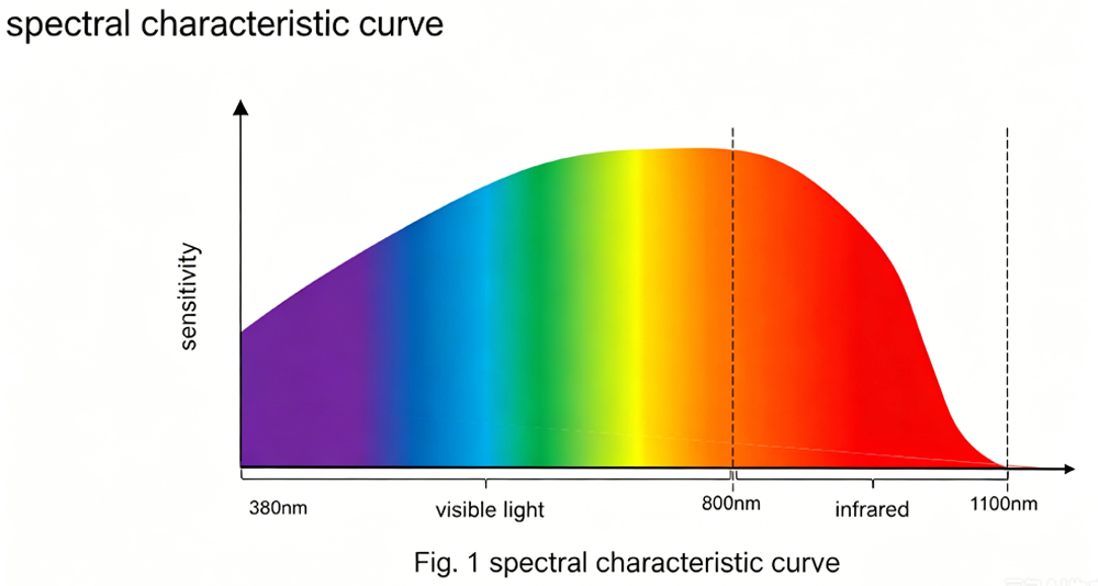
Spectral Response Range
|
380 ~ 1100 nm
|
|
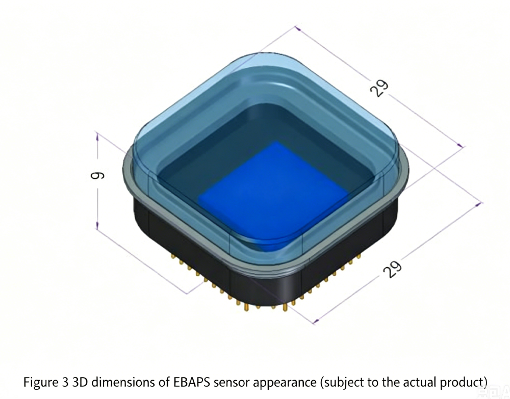
Sensor Dimensions
|
29 × 29 × 9 mm
|
|
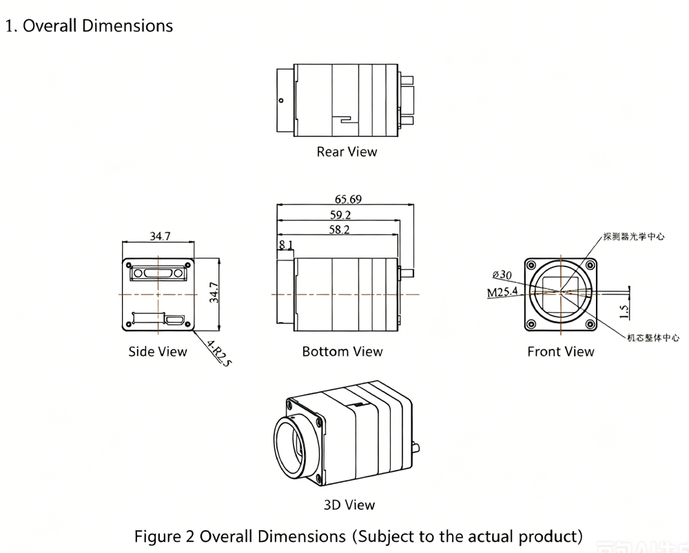
Overall Dimensions
|
≤ 34.7 × 34.7 × 60.5 mm
|
|
Sensor Weight
|
≤ 21 g
|
|
Overall Weight
|
≤ 92 g
|
|
Shutter Mode
|
Rolling Shutter
|
|
Output Interface
|
Camera Link
|
|
Power & Communication Interface
|
J30J
|
|
Power Consumption
|
≤ 1.5 W
|
|
Operating Temperature
|
-45 ~ 55 ℃
|
|
Lens Mount
|
C-Mount
|
Spectral characteristic Curve
Overall Dimensions of EBAPS module
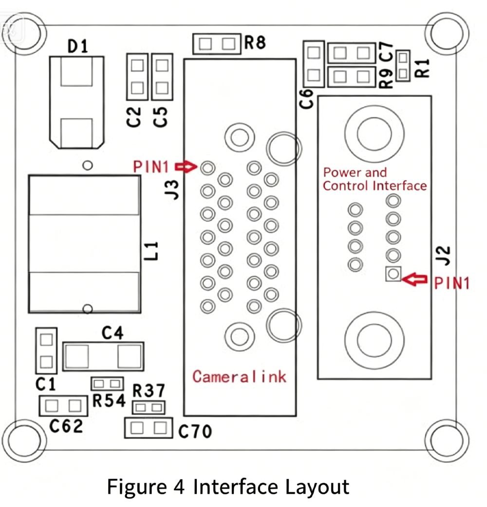
The definitions of interfaces available for user use are shown in Table 3.
Table 3 User Interface Definition
|
Interface Name
|
Reference Designator
|
Model
|
Pin No.
|
Pin Name
|
Description
|
|
Power and Control Interface
|
J2
|
J30J-9ZKNP5-J
|
1
|
VIN
|
Power Input
|
|
Power and Control Interface
|
J2
|
J30J-9ZKNP5-J
|
2, 6
|
GND
|
Power Ground
|
|
Power and Control Interface
|
J2
|
J30J-9ZKNP5-J
|
3
|
—
|
Reserved
|
|
Power and Control Interface
|
J2
|
J30J-9ZKNP5-J
|
4
|
485_A
|
RS485 A Line
|
|
Power and Control Interface
|
J2
|
J30J-9ZKNP5-J
|
5
|
485_B
|
RS485 B Line
|
|
Power and Control Interface
|
J2
|
J30J-9ZKNP5-J
|
7
|
—
|
Reserved
|
|
Power and Control Interface
|
J2
|
J30J-9ZKNP5-J
|
8
|
—
|
Reserved
|
|
Power and Control Interface
|
J2
|
J30J-9ZKNP5-J
|
9
|
—
|
Reserved
|
|
Camera Link Digital Video Interface
|
J3
|
12226-1150-00FR
|
1, 13, 14, 26, 27, 28
|
GND
|
Ground Signal
|
|
Camera Link Digital Video Interface
|
J3
|
12226-1150-00FR
|
2
|
CL0-
|
Data Signal
|
|
Camera Link Digital Video Interface
|
J3
|
12226-1150-00FR
|
3
|
CL1-
|
Data Signal
|
|
Camera Link Digital Video Interface
|
J3
|
12226-1150-00FR
|
4
|
CL2-
|
Data Signal
|
|
Camera Link Digital Video Interface
|
J3
|
12226-1150-00FR
|
5
|
CLCLK-
|
Data Signal
|
|
Camera Link Digital Video Interface
|
J3
|
12226-1150-00FR
|
6
|
CL3-
|
Data Signal
|
|
Camera Link Digital Video Interface
|
J3
|
12226-1150-00FR
|
7
|
SERTC-
|
Serial Communication Signal
|
|
Camera Link Digital Video Interface
|
J3
|
12226-1150-00FR
|
8
|
SERTFG-
|
Serial Communication Signal
|
|
Camera Link Digital Video Interface
|
J3
|
12226-1150-00FR
|
9, 10, 11, 12, 22, 23, 24, 25
|
—
|
—
|
|
Camera Link Digital Video Interface
|
J3
|
12226-1150-00FR
|
15
|
CL0+
|
Data Signal
|
|
Camera Link Digital Video Interface
|
J3
|
12226-1150-00FR
|
16
|
CL1+
|
Data Signal
|
|
Camera Link Digital Video Interface
|
J3
|
12226-1150-00FR
|
17
|
CL2+
|
Data Signal
|
|
Camera Link Digital Video Interface
|
J3
|
12226-1150-00FR
|
18
|
CLCLK+
|
Data Signal
|
|
Camera Link Digital Video Interface
|
J3
|
12226-1150-00FR
|
19
|
CL3+
|
Data Signal
|
|
Camera Link Digital Video Interface
|
J3
|
12226-1150-00FR
|
20
|
SERTC+
|
Serial Communication Signal
|
|
Camera Link Digital Video Interface
|
J3
|
12226-1150-00FR
|
21
|
SERTFG+
|
Serial Communication Signal
|
Connection Application Examples
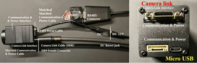
1.Hardware Connection Method
(1) Connect the Camera Link cable to the Camera Link interface.
(2) Connect the RS485 serial cable and DC12V power supply wire to the corresponding positions of the matched communication & power cable.
Alternatively, a Micro USB interface can be used for 5V power supply. The two power supply paths shall not be energized simultaneously.
2. Capture Card Configuration and Operation Instructions
2.1 Key Configuration Parameters
a) Number of channels: 2b) Pixel format: mono12 c) Pixel resolution: 1280×1024
2.2 Operation Guide (Taking IPORT-CL-U3B Capture Card as an Example)
a) Install client software: eBUS Player 64-bit.6.0.1.4876.exeb) Open the file nnvt-9b3.pvcfg, and the interface shown in Figure 6 will pop up.(If prompted to select an opening program, navigate to the folder C:\Program Files\Pleora Technologies Inc\eBUS Player and select the executable file eBUSPlayer64.exe)c) Click the play button marked by the red circle in Figure 6 to view the real-time camera video stream
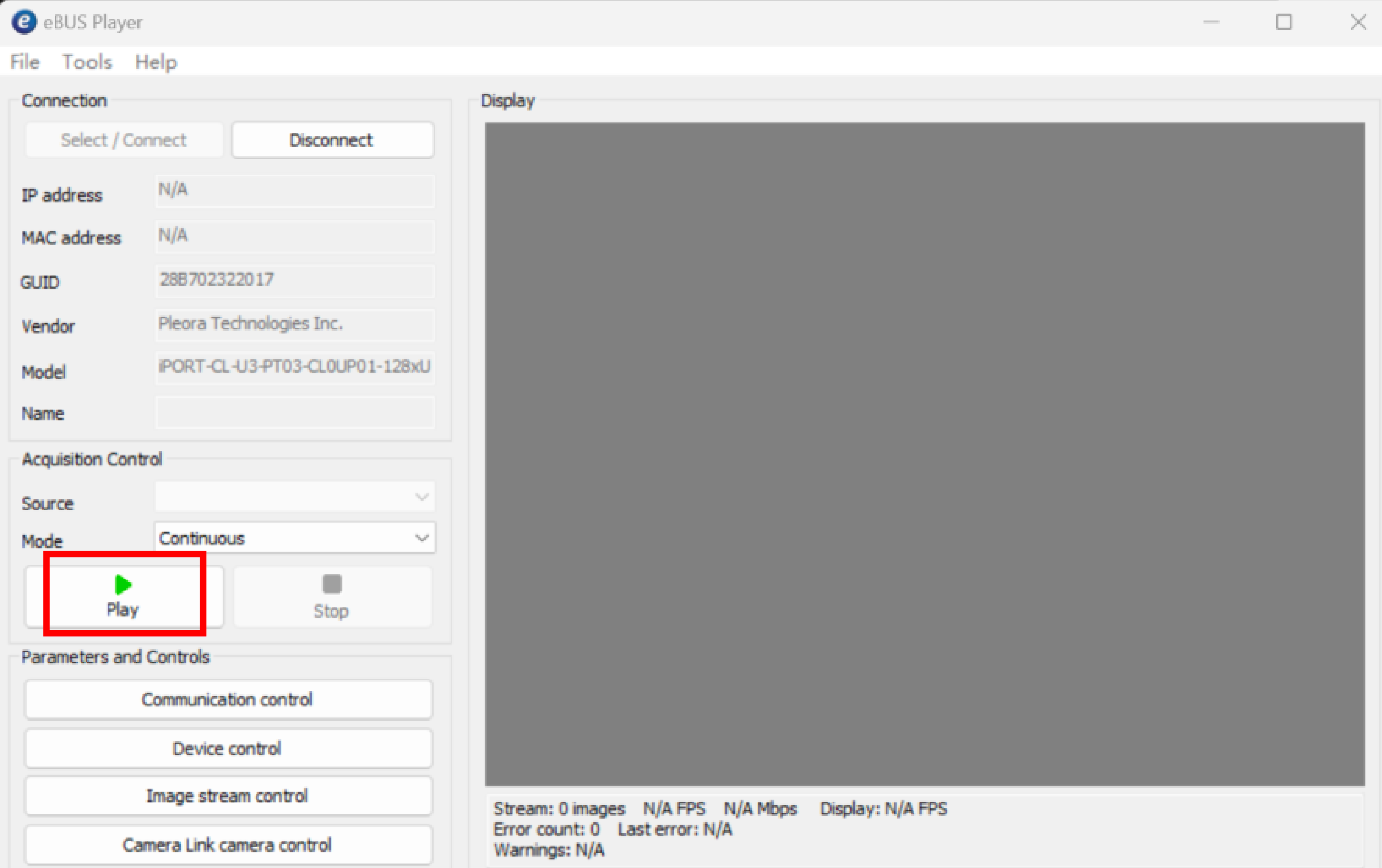
Figure 6 Capture Card Acquisition Interface
d) If image or video capture is required, click in sequence: Tools → Save Images or Videos. The interface shown in Figure 7 will then appear. Check the Enable Ima... option, then select the save path, data format (select the last option for video saving), and capture frame rate from the drop-down boxes below one by one. Select the last capture rate option unless otherwise necessary. Afterwards, click the play button to start image/video capture.
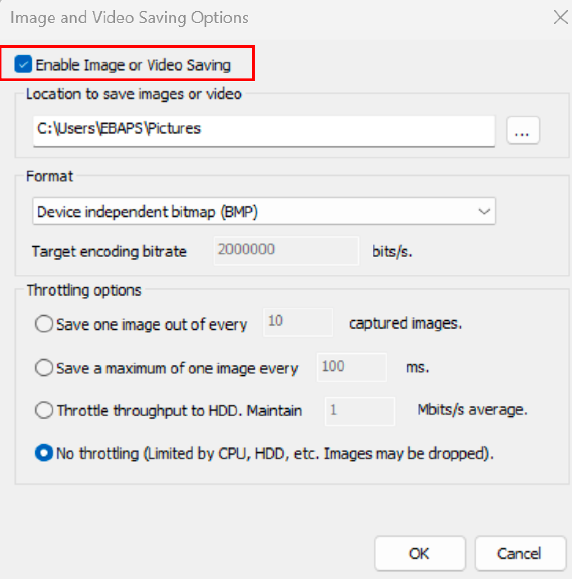
Figure 7 Tab for Video and Image Data Storage Options
Note: The above operations are performed with a USB-Camera Link capture card. You may select a suitable Camera Link capture card according to actual application requirements.
3 Connection Method of Communication Software
(1) Launch the EBAPS debugging software as shown in Figure 8. Search for and select the corresponding serial port (e.g., COM7), set the baud rate to 115200, data bits to 8, stop bits to 1, then open the serial port.(2) Adjust relevant parameters and save them according to actual application requirements.
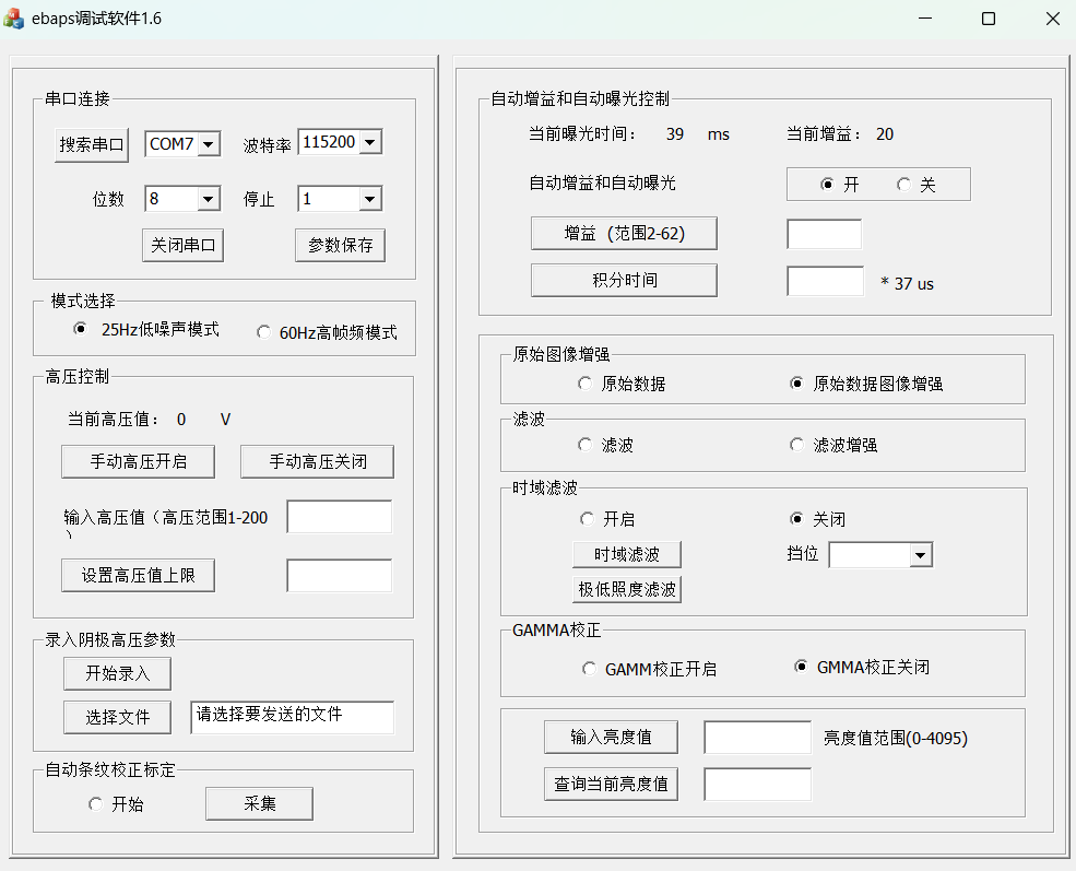
Figure 8 Debugging Software Interface
Precautions
Do not irradiate the device directly with intense light sources during normal operation in low-light environments.
Do not sharply increase voltage or adjust illuminance under the manual high-voltage operating mode.
Prevent immersion in water, exposure to rain and direct sunlight.
Do not place the device in areas with strong electric or magnetic fields.
If abnormal operation occurs during testing, cut off the power supply before troubleshooting.
Wear anti-static gloves during operation.
Engineer Manager Name: Jacky
WhatsApp/ Wechat: 0086-187 9245 6795
Email: mh_elec@126.com or jacky@mh-elec.com